Made by PoPoPyo
Thank you for your purchase. Please use this as a reference when assembling or considering your purchase.
Attention
If your skill level is such that you can disassemble the Logitech G PRO X Superlight, you can assemble it.
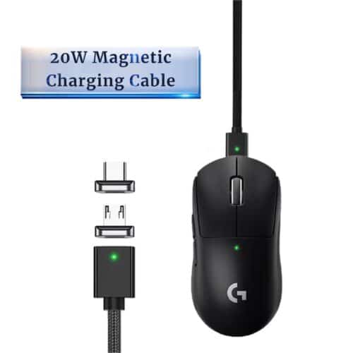
The default G PRO X Superlight charging cable cannot be used. So you need a Micro USB Type-B cable.
Upon receiving the printed materials, we recommend that you wash off the nylon powder first.
When washing off, using a toothbrush or an ultrasonic cleaner is effective.
Required Parts

Logitech G PRO X Superlight
- Main PCB
- Sub PCB
- Ribbon cable
- Battery
- Large Screws x 2
- Medium Screws x 4
- Small screws x 4

HC-KP
- Shell
- Frame
- Left click
- Right click
Tool
- Screwdriver
- Scissors (if necessary)
- Tape (if necessary)
- Tweezers (if necessary)
- Grease (if necessary)
- Thin tool (If necessary)
Assembly Instructions
- Insert the ribbon cable into the main PCB.
| Required Parts | Quantity |
|---|---|
| Main PCB | 1 |
| Ribbon cable | 1 |

2. Securing the main PCB to the shell. In this case, use two large screws in the holes circled in red. It does not matter if the front side of the main PCB floats.
| Required Parts | Quantity |
|---|---|
| Main PCB ※Includes accompanying parts | 1 |
| Large Screws | 2 |
| Shell | 1 |

3. Securing the side button portion of the ribbon cable into the location shown in the image. If the adhesive on the back side is weak, use double sided tape or similar to attach the cable.
| Required Parts | Quantity |
|---|---|
| Shell ※Includes accompanying parts | 1 |
| Double-sided tape ※If necessary | 1 |

4. Insert the battery and attach it to the battery holder of the frame. The surface to be attached is the back side of the frame.
| Required Parts | Quantity |
|---|---|
| Shell ※Includes accompanying parts | 1 |
| Frame | 1 |
| Battery | 1 |
| Double-sided tape ※If necessary | 1 |

5. Pass the part of the ribbon cable to be inserted into the sub PCB through the red mark in the image.
| Required Parts | Quantity |
|---|---|
| Shell ※Includes accompanying parts | 1 |
| Frame ※Includes accompanying parts | 1 |

6. Securing the framework. Use the two middle screws at the locations circled in red in the image.
Please refer to the detailed instructions below the image for further guidance.
| Required Parts | Quantity |
|---|---|
| Shell ※Includes accompanying parts | 1 |
| Frame ※Includes accompanying parts | 1 |
| Medium Screws | 2 |


7. To secure the sub PCB to the frame, use four Small screws at the locations marked with red circles. Take care to ensure that the sub-PCB remains as stable as possible without tilting. Additionally, if necessary, apply grease to the wheels.
| Required Parts | Quantity |
|---|---|
| Frame ※Includes accompanying parts | 1 |
| Sub PCB | 1 |
| Small screws | 4 |
| Grease ※If necessary |

8. To secure the parts of the left and right click parts to the frame, use two medium screws at each location marked with red circles.
Please refer to the detailed instructions below the image for further guidance.
| Required Parts | Quantity |
|---|---|
| Frame ※Includes accompanying parts | 1 |
| Left click | 1 |
| Right click | 1 |
| Medium screws | 2 |
| Tape ※If necessary |


9. Put the universal sole. Any feet with a diameter of 8mm or less can be used

10. Assembly complete.

Creator:ぽぽぽーよ
Twitter: https://twitter.com/Po_Po_Pyo_
Leave your comment
Related posts